Taxonomy of Virtual Spaces
 |
| Wardrip-Fruin, Noah. (2020). How Pac-Man Eats. Cambridge, Massachusetts: The MIT Press. |
Today, I return to the topic of spatial models in digital games. In his book How Pac-Man Eats, Noah Wardrip-Fruin identified two different models of space that all digital games follow: Continuous Spatiality and Discrete Spatiality. These models are equal to what Espen Aarseth calls Geometrical Topology and Topological Topology, respectfully. I blogged about Aarseth's topologies previously and, although they convey the same concepts, I prefer the Wardrip-Fruin's intuitive naming structure (try saying "topological topology" five times fast).
As republished in my previous blog post, I describe the differences between the two spatial models in my paper, A Taxonomy of Virtual Dimensions (Rowe, unpublished):
Two of the earliest contenders for the title of “first video game” are Christopher Strachey’s Draughts (1951) and Willy Higinbotham’s Tennis for Two (1958). Each title is pioneering in its own right: Draughts is probably the first game a computer game program and the first computer game with graphics on a cathode ray tube while Tennis for Two is the first known two-player action game. Analyzing these two games for their presentation of spatiality would help us articulate what is important about these two works.
Discrete Spatiality
 |
| Draughts (Christopher Strachey, 1951) |
Draughts has what Noah Wardrip-Fruin would describe as Discrete Spatiality. The entire game space is “divided into non-overlapping spaces, and each game action involved moving a piece from one discrete space to another with no in-between position available or meaningful” (Wardrip-Fruin, How Pac-Man Eats, 2020). Each square on the checkerboard is a separate point in space. The checkers do not move between the points as there is no “space” to move through. Many strategy games work in this same manner today. Sprites may animate as if they are moving between spaces, but the game only treats them as being in one space or another, never overlapping multiple spaces.
Continuous Spatiality
 |
| Tennis for Two (William Higinbotham, 1958) |
Conversely, Tennis for Two is the first example of Continuous Spatiality in a digital game, which “requires that there be many potential positions in the virtual space (so many that moving between them creates a feeling of continuousness)” (Wardrip-Fruin, 2020). It is also worth noting that time in the game is discrete (time tracked by alternating game turns of any length) or continuous in each example.
Any digital game can be classified as using one of these two spatial modes: discrete or continuous.
Spatial Model Classification Edge Cases
Ataxx
 |
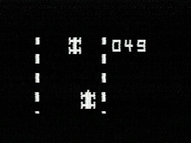
| Ataxx (Leland Corporation, 1990) |
Ataxx is a turn-based arcade game played on a 7 x 7 grid and is similar to the board game Othello. There are only 49 possible discrete spaces in the game, but the player pieces animate as they split and move to those spaces, giving the impression of a continuous space. However, with the clearly turn-based nature and board game-like structure of the game, it should easily be classified as using a discrete spatial model.
Q*bert
 |
| Q*bert (Gottlieb, 1982) |
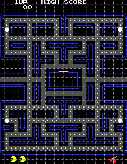
Pac-Man
 |
| Pac-Man (Namco, 1980) |
A fast-paced action game like Pac-Man seems like a prototypical example of continuous space with characters smoothly chasing each other around the maze.
 |
| The discrete tile grid behind Pac-Man's collision detection, from "Pac-Man Dossier" (Jamey Pittman, 2009) |
While sprite visuals may appear in many positions on the screen, each game object's collision is tracked on a discrete grid of 8 x 8 pixel tiles, as illustrated above. Two game objects collide when they are on the same tile at the same time.
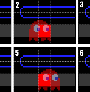 |
| Blinky moves 6 pixels to the right, but he remains in the same collision tile, from "Pac-Man Dossier" (Jamey Pittman, 2009) |
Note that the game sprites are much larger than each collision tile. The character is considered to move from one tiles to another when its center point overlaps the next tile in the grid. This simple system reduces the computational load of detecting collisions between many moving objects and works perfectly... almost all of the time.
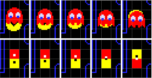 |
| Illustration of the "pass-thru bug," from "Pac-Man Dossier" (Jamey Pittman, 2009) |
On rare occasions, two game characters moving in opposite directions may pass through each other without colliding if both characters move into different tile grids at the same time, essentially swapping positions on the same frame. Pac-Man players sometimes have the experience of dodging past an enemy ghost monster in this way, miraculously saved from certain doom.
Conclusion
 |
| Freeway (RCA, 1977) |
Consider the RCA Studio II game console with its 64 x 32 screen resolution. Even with limited possible positions in visual space, many games on the system are designed around a continuous spatial model (as illustrated by Freeway, above). Contrast this with Civilization V, a discrete-space strategy game with game maps that are up to 128 x 80 tiles in size. Civilization V has a higher density of possible spatial positions, but would not be treated as a continuous spatial model. So, it is not just the number of spatial positions that creates a continuous spatial model.