Monday, July 31, 2023

Cartesio: A Spatial Projection Tool from the Past

Taxonomy of Virtual Spaces

My new digital project will enable a user to simulate many different types graphics seen in video games. These graphic styles are classified by different types of planar geometric projections (or just "projections").

Some methods can be unclear, especially with discrepancies between using Primary Geometry and Secondary Geometry methods to illustrate game images. My methodology uses a primary geometry model, in which the entirety of the rendered virtual space, objects, "camera," and projection plane can be mapped out into a continuous spatial relationship. The secondary geometry model focuses only on the composition of the resulting image on the picture plane. Most artists, especially game artists before the advent of 3-D modeling, tend to work with the secondary geometry model. Understandably, visual aesthetics are far more important than spatial fidelity.

Once I have a grasp of the math behind the model, I can create a simulacrum of the spatial structure. 3-D projections are relatively easy to "reverse engineer," whether rendered in 1-point, 2-point, or 3-point perspectives. Orthographic projections are easy due to their simplicity - always using one of 6 possible facings. However, the axonometric and oblique projections can be more challenging. Is there an easy way to determine the "camera angle*" for a trimetric game like Crystal Castles?

* I use the term "camera" loosely here, as a camera would suggest a singular, subjective station point that the projectors converge upon. In parallel projections, there is no convergence and no station point, yet Unity still uses an "orthographic camera" for its parallel projections. "Camera" is used here to convey the angle from which a scene is viewed.

I needed a tool to assist me in calculating these primary geometry structures. The shear settings in modern 3-D editors like Maya aren't the same. I looked for software that would allow me to quickly change projection settings and compare them to the methods seen in games.

I learned about such a tool from the article "Axonometric Projections - A Technical Overview" (2009, Thiadmer Riemersma, chapter 10 from Advanced Game Programming: A GameDev.net Collection, Cengage).

Cartesio

Cartesio (1997, Camillo Trevisan, computer program, v. 3.03e) is just such a tool. It was created by Camillo Trevisan, former associate professor (now retired) at Università Iuav di Venezia, an architectural school in Venice, Italy. It is a graphic tool that lets the user render simple geometric shapes using many different projection methods with user-customizable parameters. Better still, it renders the orientation of the picture plane to better clarify the overall primary geometry model (see image below, with picture plane rendered in cyan on small windows to right of image).

Example screen shot of Cartesio.

Cartesio is free to use for personal use, but had two drawbacks for me when getting started:
  1. Some of the text in the English version of the program is still in Italian. I can't read Italian.
  2. This program was written in 1997 and no longer functions in modern Windows environments.
The first problem wasn't too bad, though the English help files certainly read like translated documents. The second problem required me to set up a virtual machine on my PC, install a copy of Windows 95 (and dig up my registration), then "burn" Cartesio to an iso virtual CD image in order to install it.

Below are some examples of how I've used Cartesio to image several parallel projection methods, rendering a simple cube for clarity.

Orthographic Projection

Orthographic graphics in Pac-Man (1980, Namco, arcade game).

Orthographic projection is probably the easiest graphic style to understand. Game objects and environments are presented in a "flat" view, usually as if seen from above, the side, or from the front. Many early digital games use this form of projection.

Pac-Man is an example where different conceptual planes ("The Game FAVR: A Framework for the Analysis of Visual Representation in Video Games" by Dominic Arsenault, Pierre-Marc Côté, and Audrey Larochelle (2015) Loading…Journal of the Canadian Game Studies Association, vol.9, no.14) in the same game image may be projected in different facings (or "camera directions") while the overall image retains a sense of cohesion. All video game imagery is a hybrid collection of smaller images displayed and moved around a screen in order to generate a complete picture of the agents and environment of a virtual world. Those hybrid images may be "seen" from different angles from each other, yet we still understand the image as projecting a single, virtual space. In Pac-Man, the characters and fruits are seen from an "elevation" view, either from the side (the titular Pac-Man always appears in profile) or from the front (ghost monsters and bonus fruits). However, the environment appears from and overhead "plan" view as the maze is navigated like a floor plan or road map. Most players accept the game's spatiality without a thought to this incongruity.

Orthographic projection in Cartesio

True isometric graphics in Monument Valley (2014, ustwo Games Ltd., mobile phone game).

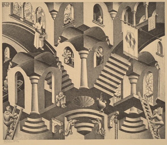
In the modern era, games like Monument Valley employ true isometric graphics to render worlds that are navigable along three different axes. This game takes advantage of some quirks of this art style to render "impossible" worlds, optical illusions that could not exist in physical space, yet create a cohesive image. The team was influenced by Dutch artist M.C. Escher, who mastered the use of isometry and other techniques to convey his impossible worlds onto 2-D planes.

Convex and Concave (1955, M.C. Escher)

"Isometric" is an overused term used to describe many different types of game graphics. As Audrey Larochelle puts it, "Because it is the most common form of axonometric projection, isometric has often taken the role (and the name) of a vast number of other categories of visual representation" ("A New Angle on Parallel Languages"GAME: The Italian Journal of Game Studies, vol. 1, no. 2 (2013), pp 35-36). Here, I clarify the use of "true" isometric projection, where the z-axis is presented vertically on the screen and the x-axis and y-axis are 120° from the z and from each other.

Where "isometric game" is a term that has been used exceedingly by game developers, players, and journalists for decades, games using "true" isometric angles has been a rarity until high resolution graphics became commonplace. Other forms of parallel axonometry ("pixel" dimetric and trimetric below, for example) are easier to render with square tile-based graphics, which a majority of early games used to render game environments.

"True" isometric projection in Cartesio

True isometric projection presents the virtual environment as if the viewing "camera" were rotated 45° in the z-axis from the environment's "front" face and looking down 35° off from parallel to the XY plane. This presents the viewer with three different faces, or angles, of each game object equally, with no face given more importance than another face.

"Pixel" Dimetric Projection

"Pixel" dimetric graphics (1:2) (a.k.a. pixel isometric) in Q*bert (1982, Gottlieb).

Warren Davis' Q*bert (1982, Gottlieb, arcade game) is one of the first games to use "pixel" dimetric graphics
, a system that can convey a sense of three dimensions with tile-based environment graphics. This pioneering style of graphics had only been used in a few games by the time Q*bert debuted (notably in Treasure Island (1981, Data East, arcade) and Zaxxon (1982, Sega, arcade)).

Q*bert with grid showing how cubes are constructed from repeating 8x8 pixel "blocks."

Warren Davis was also influenced by M.C. Escher in the creation of Q*bert (2019, Warren Davis, You Can't Call It @!#?@!, DIYWBD, Inc., pp 37-40). He saw a screen of "repeating Escher-like cubes" (pg. 37) created by Gottlieb artist Jeff Lee. Davis recognized and appreciated the "Escher-ness of the design" (pg. 38) and realized that the pseudo-3D cubes (which he also refers to as "isometric projection" and "2 1/2 D") conveyed a convincing sense of depth which was a rarity in games at the time. Gottlieb's arcade game hardware could draw the background art for a game screen as a 30x32 array of 8x8 pixel-sized "blocks" (see above image). This design uses a small set of 8x8 pixel tiles with different color palettes to serve as the blocks, creating a detailed world with very few resources.

From Visual Storytelling in Games, Part 1: Space (Rowe, unpublished)

While it isn't a true isometric axonometry, this graphics style came to be known as "isometric," along with other, similar axonometric projections. In Q*bert's "pixel dimetric" graphics, the z-axis is drawn vertically on the picture plane. The x-axis and y-axis are drawn at ~26.56° from the horizontal (arctangent(0.5)°). This means that the x and y lines are drawn at a 1:2 rise over run ratio.

From Visual Storytelling in Games, Part 1: Space (Rowe, unpublished)

The 1:2 ratio has the advantage of making a "nice" line in pixel graphics. In the days before high resolution screens allowed for anti-aliasing, thin lines at certain angles often led to the dreaded "jaggies." A 30° isometric angle would look more like a jagged lightning bolt than a straight line. A ~26.56° dimetric angle, on the other hand, creates a smooth 1:2 line.

"Pixel" dimetric projection in Cartesio

"Pixel" dimetric is close to "true" isometric, with the viewing "camera" rotated 45
° from the game's front face and looking down at ~30° from parallel to the XY plane. This tends to present the left and right faces of game objects as slightly larger than the top faces of those objects.

"Pixel" Trimetric Projection
Trimetric graphics (1:1, 1:4) in Crystal Castles (Atari, 1983, arcade game)

One year after Zaxxon and Q*bert, Atari released Crystal Castles, a game about exploring 3-D mazes drawn to the screen with trimetric projection. Like those earlier games, the z-axis is drawn vertically on the screen. However, the x-axis and y-axis are drawn at 1:1 and 1:4 ratios, giving the impression of looking at the world at an uneven rotation. One axis recedes into the picture plane at a steeper angle than the other axis. There are many different ways of projecting trimetric graphics, but I will refer to this (1:1, 1:4) ratio as "pixel" trimetric.

Even the game's programmer, Franz Lanzinger, refers to Crystal Castles' graphics as "isometric" (Lanzinger, Classic Game Design, 2014, Mercury Learning, pg. 241).

"Pixel" trimetric projection in Cartesio

This "pixel" trimetric graphics presents the game as if the viewing "camera" was rotated about 30
° from the environments front face, looking down at about 33.5° from the XY plane. There are other forms of trimetric projection that may project their worlds and somewhat different angles.


Friday, July 14, 2023

Digital Project Plans

Taxonomy of Virtual Spaces

Over this summer, I am starting a new digital project to explore the planar geometric projection options I defined in my Taxonomy of Digital Spaces. I plan to create a digital game where the spatial qualities of the game can be changed on the fly, in order to partially show specific spatial paradigms that, I argue, are unique aesthetic qualities of digital games.

The final project should be much like a virtual museum, where different spatial concepts may be explored and examined in an interactive manner. This will be similar to another project I created a few years ago, Traversing Virtual Dimensions (after which this blog is named). In Virtual Dimensions, the player is able to experience some of the earliest developments of a player avatar able to navigate through virtual space in digital game history. Unlike that project, Taxonomy will allow a player to set different methods of projection for the virtual environment and navigate that environment in a game-like manner.


The following are some screen shots of my initial tech prototype:

Game environment test with oblique projection.

Game environment test with orthographic projection.

Game environment test with perspectival projection.

I am using the Unity game editor as my development environment because I know that game engine very well and can work in it relatively quickly. My tech prototype uses the Kenney Game Assets All-in-1 asset pack for game characters. The ability to change the type of projection with Unity's camera is thanks to Art Leaping's Camera Perspective Editor scripts and the background cityscape seen in the prototype. All assets are used under license.

Creating all of the custom art needed, by hand, to project the same environment in many different methods of projection would be an insurmountable amount of work for one person. While I would relish the chance to create several different tile sheets of environmental sprite art and matching 3-D geometry as an exercise in different digital game art styles, I simply don't have the time to tackle that and everything else the game needs. However, if I am able to replicate 2-D game art methods by using a modified game camera, I can project the same set of 3-D scene objects to the screen in many different ways with different camera settings. Adapting to this technology should save a lot of effort.

The first goal for the project is to make project where the navigable environment may be changed to use the different methods of projection outlined in my research. The next step is to be able to change the other two conceptual image planes on the screen: the agents (characters and interactive elements) and the background/foreground objects. Once that is complete, I plan to have different player avatar characters that can move around the virtual environments in as-yet undefined methods of player affordances. These two elements together (the graphical spatial qualities and the player navigation affordances) can be used to define a game's spatial paradigm.

The final goal of my research is to define game aesthetics by their spatial qualities dealing with the embodied phenomenon of navigating virtual spaces, a cyberkinaesthetic experience. I posit that specific aesthetic trends and styles can be traced through our young art form's history and create a new diachronic "art history" of digital games in the process.

Planar Geometric Projections

Taxonomy of Virtual Spaces

Part of my research is in defining a framework and vocabulary for analyzing and describing the concept of spatiality in digital media (especially in digital game environments). This "Taxonomy of Virtual Spaces" (Rowe, unpublished) is one of the tools for recognizing and clearly defining the aesthetic styles of digital games that I call spatial paradigms. How are these virtual spaces of the game world projected as 2-D images onto the display screen?

"Projection" is used here in the sense of a virtual 3-D object or scene that is projected (transformed) into a 2-D image on a screen. This may be accomplished by a computer rendering 3-D object data into a 2-D graphics matrix or a human artist drawing a 2-D game image (such as a sprite or a tile) using techniques that may give an object visual depth cues (such as axonometric or oblique drawing methods).

This system was initially based on the pioneering work by Dominic Arsenault, Audrey Larochelle, and other researchers at the University of Montreal that led to their "Game FAVR" system of analyzing digital game graphics ("The Game FAVR: A Framework for the Analysis of Visual Representation in Video Games" by Dominic Arsenault, Pierre-Marc Côté, and Audrey Larochelle (2015) Loading…Journal of the Canadian Game Studies Association, vol.9, no.14). I briefly wrote about Game FAVR on this blog before. It is a system that takes the inherently hybrid nature of all video game imagery into account, but it is specifically a means of analyzing the construction of graphic images, not game spatiality.

Game FAVR divides a video game image into three conceptual "image planes:" the characters and interactive elements (agents), the environment, and the background/foreground elements. Each of these different frames may be (and often are) rendered to the screen in different methods. I adapted the Game FAVR system to analyzing projected spatiality (since game space is presented graphically) and refined the categories of graphic techniques (planar geometric projections) used in games.

My latest update to my "family tree" of rendering methods is as follows:

Planar Geometric Projections from "A Taxonomy of Virtual Spaces" by Tony A. Rowe (unpublished)

This chart is only a current revision and is not meant to be exhaustive. It does not include curvilinear perspective, cartoon structures), divergent perspective ("reverse perspective"), or stereographic projection (usually used in cartography). I may expand the chart with these other methods, if needed. This may be more categories than I need for my study, but I would rather start with more details than I need and trim back later (for example, the vertical/horizontal oblique and vertical/horizontal orthogonal projections are almost identical).

The terms above are not universally agreed upon in the English-speaking world. I listed alternate or more specific terms (in gray italics) under each category, as appropriate. Different words may have different meanings to different disciplines and in different contexts. Game developers and journalists are also known for adapting and using terminology in an ad-hoc manner. There are many different graphic methods or camera angles that may all be described as "isometric," "3/4 view," "2.5-D," or "top-down" by different people. From my own studio work, I thought that "hit spang" (the visual effect of a projectile colliding with an object) was a standard visual effect term. Not so, it seems to have been a term that was adapted by my team and carried forward on later projects.

Take the term "axonometric," for example. I recently went through the work of defining what axonometric means, writing an overview of the history of axonometric drawing, and finally determined there are multiple ways of understanding the geometry behind a projection, or drawing, of an object. In the end, I adapted the "primary geometry" method of classifying graphic projections, as that is the standard method used in computer graphics for decades. However, I have noted a "secondary geometry" relationship between the three axonometric and some oblique projections in my chart, above (see the dashed line box). These are all methods of "pictorial" drawing (to use a term from engineering) and may otherwise be defined as "axonometric."

In addition to the projection methods, the three conceptual image planes (agents, environment, background/foreground) are classified by projection angle (the "camera angle" on the object). There are also examples of image planes that are "rendered" by other methods, such as symbols or text description.

The projection methods are just one factor of my taxonomy method. A game's spaces are further classified by its frame mobility (how the "camera" moves across the environment), the topology of the game world, the dimensionality of navigable game space, and other details like gravity.

A game's spatiality goes hand-in-hand with a game player's affordances to navigate that space to create what I call a spatial paradigm.

Wednesday, July 12, 2023

Clarifying: Axonometry, pt. 3

Taxonomy of Virtual Spaces

In part one of this series, I collated the qualities that define an axonometric projection.

An axonometric projection is one in which a rendered object can be measured across all three axes (x axis, y axis, and z axis).

The object's axes are not parallel and not orthogonal to the projection plane, allowing three faces of the object to be seen in the image.

It is a type of parallel projection in which a 3-D object is transformed into a 2-D image on the projection plane.

It is an affine transformation, meaning that the angles between lines in the image may differ from those found on the object, but straight lines remain straight and parallel lines remain parallel.

Being a parallel projection, lines do not converge and objects do not reduce in size with distance from the projection plane.

In part two of this series, I explored the histories of two different rendering styles that are both referred to as "axonometric" and both match the above description: oblique projection and isometric projection. Now, for a look at what a "projection" means in terms of rendering an image.

Planar Geometric Projections


Planar geometric projection is a geometric construct that seeks to define the abstract act of rendering a drawing of an object. In a planar geometric projection, points on a 3-D object are "projected" onto a 2-D projection plane. The geometry of the 3-D object is transformed in the process. How it is transformed depends on the projection method used to render the object on the plane.

There are three essential elements to this geometrical model (adapted from Drawing Distinctions by Patrick Maynard (2005) pg. 21):
  1. One or more objects (usually straight-edged and cornered)
  2. A planar surface on which the projection takes place
  3. Projectors, straight lines that coordinate points between the other two elements
The illustration above shows a model of a perspectival projection (often known as linear perspective, a term coined by Brook Taylor in the 18th century (Maynard (2005) pg. 20). The object is a cube. Projector lines are projected from the corners of the cube, converging at the observer's eye (also called the station point, a stationary point from which the perspectival view is seen). The corners of the 2-D image of the cube are rendered at the points where the projectors intersect with the projection plane.

Figure 3-6a. Construction of an isometric projection from "Planar Geometric Projections and Viewing Transformations" by Ingrid Carlbom and Joseph Paciorek, Computing Surveys, vol. 10, no. 4 (1978) pg. 479

An isometric projection is a parallel projection where the projectors are all in parallel (not converging on a station point, or, imagining a station point at infinite distance) and are orthogonal (at 90 degrees) to the projection plane. None of the axes are in parallel with the projection plane, allowing three sides of the object to be rendered.

Figure 3-11a. Construction of an oblique projection from "Planar Geometric Projections and Viewing Transformations" by Carlbom and Paciorek (1978) pg. 482

An oblique projection is a parallel projection where the projectors are all in parallel and are at an oblique angle to the projection plane (often at 45 degrees). Two axes are parallel to the projection plane but, due to the oblique angle of the projectors, three sides of the object are rendered.

Primary Geometry and Secondary Geometry

The geometric projection model described above is what Peter Jeffrey Booker distinguishes as "Primary Geometry." This is the 3-D geometry of the lines of projectors from the scene to the eye of the viewer and the intersections of those projectors with a projection plane in order to form an image. He also notes "Secondary Geometry" as the 2-D geometry of the projection plane, itself (from A History of Engineering Drawing (1963))

Booker decried the primary geometry method as having "little practical significance or psychological reality" (as summarized in Art and Representation by John Willats (1997) pg. 38). 
"The modern method, described above, of defining the various drawing systems in terms of three-dimensional projective geometry was invented during the nineteenth century by textbook writers who wanted to give engineering drawing an air of authority by bringing it into line with Renaissance accounts of linear perspective. The idea of orthogonal projection as a variety of perspective with the object moved to an infinite distance away is a mathematical fiction, and engineers rarely, if ever, think of the system that way." Willats (1997) pg. 38
Fig. 2.1 Classification scheme for the projection systems, based on primary geometry. Adapted from British Standard 1192 (1969) from Willats (1997) pg. 39

Willats (still arguing on Booker's behalf) also purports that "defining the various projection systems in terms of their primary geometry leads to a classification scheme which seems counter-intuitive" ((1997) pg. 39). He presents the British Standard 1192 of drawing classifications for technical drawings as such a system. Isometric (and related methods) are classed as a parallel projection with orthogonal methods, based on the fact that their projectors are orthogonal to the projection plane. Oblique (and axonometric, as defined in architecture) methods are in a separate parallel projection class based on the fact that their projectors are oblique to the projection plane.

Willat's classification scheme for projection systems based on secondary geometry (as adapted in Drawing as Transformation: From Primary Geometry to Sedondary Geometry by Howard Riley (2001))

Willats instead proposes a new system based on secondary geometry, focusing on the picture surface instead of an abstract system of projection. Here, orthographic refers only to rendered objects that face in parallel to the picture plane. Oblique and isometric are grouped together as methods that render three sides of an object that is at an oblique angle to the picture plane (note that Willats includes a few new oblique definitions first described in Perspective and Other Drawing Systems by Fred Dubery and John Willats (1983) pp 21-28).

Conclusion, and What's Right for Me

Willats rightly cites the primary geometry system of projection as unintuitive and not really how people think about drawing images.

However, my study is in computer graphics and there are a lot of cases where this method is how the computer makes a 2-D image from 3-D data. Graphics shaders make calculations both in eye-space (coordinates on the screen, akin to secondary geometry) and scene-space (coordinates in the virtual world, akin to primary geometry). The digital tools I wish to use in order to affect camera perspective in my digital project also function in a similar manner.

Figure 3-1. Classification of projections from "Planar Geometric Projections and Viewing Transformations" by Carlbom and Paciorek (1978) pg. 475

Insted, the taxonomic system I use is heavily based on the classification system found in "Planar Geometric Projections and Viewing Transformations" by Ingrid Carlbom and Joseph Paciorek, Computing Surveys, vol. 10, no. 4 (1978). This system has been an established standard in computer graphics for decades, and was incorporated (and slightly expanded upon) into Computer Graphics: Principles and Practice, Second Edition by Foley, van Dam, Feiner, and Hughes (1990) pg. 237. This system also matches the one adapted by the University of Montreal academics in their studies of digital game graphics (see "A New Angle on Parallel Languages" by Audrey Larochelle, GAME: The Italian Journal of Game Studies, vol. 1, no. 2 (2013) and "The Game FAVR: A Framework for the Analysis of Visual Representation in Video Games" by Dominic Arsenault, Pierre-Marc Côté, and Audrey Larochelle, Loading…Journal of the Canadian Game Studies Association, vol.9, no.14).

In this classification system, "axonometric" refers to isometric projection and its kin (dimetric and trimetric). Oblique is a separate classification based on the obliqueness of their projectors.

More on my taxonomy system in another blog post...

History: Axonometry, pt. 2

Taxonomy of Virtual Spaces

In part one of this series, I collated the qualities that define an axonometric projection.

An axonometric projection is one in which a rendered object can be measured across all three axes (x axis, y axis, and z axis).

The object's axes are not parallel and not orthogonal to the projection plane, allowing three faces of the object to be seen in the image.

It is a type of parallel projection in which a 3-D object is transformed into a 2-D image on the projection plane.

It is an affine transformation, meaning that the angles between lines in the image may differ from those found on the object, but straight lines remain straight and parallel lines remain parallel.

Being a parallel projection, lines do not converge and objects do not reduce in size with distance from the projection plane.

Why Axonometry?

Many of the above qualities make axonometric projection an ideal system for defining an object for manufacture or construction. The relative lengths of each axis is preserved, so such a pictorial drawing (showing three sides of an object as a complete form) can also be used to measure each axis for the purpose of building a final product.
"Axonometric projections are used in catalog illustrations, Patent Office records, piping diagrams, furniture design, machine design, and structural design." from "Planar Geometric Projections and Viewing Transformations" by Ingrid Carlbom and Joseph Paciorek, Computing Surveys, vol. 10, no. 4 (1978) pg. 474
Two different forms of axonometry were developed by artists in China long before they were completely adapted by Europeans.

Oblique Axonometric History

Elevation oblique projection in detail from Along the River During the Qingming Festival (18th c. reproduction of 12th c. original) scroll painting, as cited in "Axonometric Projections - A Technical Overview"

Chinese painters developed an oblique rendering style for their landscapes painted on incredibly long scrolls (the image detail above is but a tiny fraction of Along the River During the Qingming Festival, click the links above to see it in its entirety). The physical dimensions of their medium simply wouldn't work with the sort of linear perspectival rendering techniques that developed in the Italian Renaissance. This "Chinese Perspective" (something of a misnomer, as its was also adopted to great effect by artists in Japan and elsewhere) that may have evolved from Chinese architecture could portray a vast amount of terrain and present not just a single event from a single perspective, but a story that is laid out across space and time in a panoramic view. Walking the full length of one of these scroll paintings is not unlike looking out of a moving train and viewing the landscape beyond the window pane. At each point along the scroll, the viewer can experience a comprehensible scene with a clear sense of spatiality.

Note that this method renders one major face (and thus, two axes) of an object (such as a building) as parallel to the projection plane. This breaks with the second line of the definition laid above, that an object's axes may not be parallel to the projection plane. This part of the definition is needed in order to make three sides of an object visible, as a pictorial rendering (to use an engineering term). If this was an orthogonal projection, the receding edges (the orthogonals) would not be rendered as they would fall into the "z-space" of the image at 90 degree angles to the projection plane (yes, ironically, there are no orthogonals rendered in orthogonal projections). However, an oblique projection can render the faces that would normally be hidden at an oblique angle from the forward-facing face of the object. So, either the definition is wrong or an oblique style should not be considered as "axonometric" in this definition. More on this in the next post.

This Chinese style of "border painting" was introduced to Europeans in the 17th century, where it later became known as axonometric. It was probably named somewhere in continental Europe, where the formal geometric properties of this oblique method (defined above) made it well-suited for artillery, cartography, gem cutting, and other purposes ("Axonometry: A Matter of Perspective" by Jan Krikke (2000) pp 7-8).

Plan de l'abbaye de Port-Royal des Champs by Louise-Magdaleine Horthemels (ca. 1710)

This method was also adapted for use in architectural imagery in Europe by starting with a plan view of a structure, rotating it by 45 degrees, then drawing the verticals of the structure at their true, scaled lengths (a technique also known as "military oblique"). 

Construction in Space-Time II by Theo van Doesburg (1924)

The De Stijl art movement, founded in 1917 by Dutch artists Theo van Doesburg and Piet Mondrian, brought a strong architectural influence and oblique rendering to modern art as constructions of space and time.

Le Corbusier and Mies van der Rohe followed suit, and this oblique axonometry became "nearly emblematic of modernist architecture, and it has since become an essential technique for architects and designers throughout the world" (Krikke (2000) pg. 9).

Isometric Axonometric History

Orthogonal isometric axonometry in Romance of the Three Kingdoms (ca. 15th c.)

Chinese artists also developed an isometric style of rendering objects in space, as seen in the book illustration above. Whereas oblique projections always render one face (and two axes) of an object as parallel to the projection plane with the receding orthogonal lines rendered at an oblique angle, isometric projections render all three axes of an object at equal oblique angles to the projection plane. No face nor axis is parallel to the projection plane. This produces a more "natural" construction of space (at least, to a western viewer used to Cartesian perspectives of the Italian Renaissance), but loses the 90 degree angles between lines on major faces of objects. Note that there are no 90 degree angles in the illustration above, yet the viewer "reads" the tiles, table, steps, and walls as having rectangular shapes.

Fig. 9 from "On Isometrical Perspective" by William Farish (1820)

In the west, William Farish defined isometric axonometry in his paper "On Isometrical Perspective" (1820) in response to engineering and manufacturing needs of the industrial revolution (although there were hints at orthogonal axonometry centuries earlier, such as Piero Della Francesca's "Libellus de Quinque Corporibus Regolaribus" (1490), as described by Massimo Scolari in Oblique Drawing (2012) pg. 217 (image on pg. 214)). It is unknown if he was inspired by Chinese book illustrations from centuries earlier that used the same method of projection (Krikke (2000) pp 8-9).

Convex and Concave by M. C. Escher (1955)

Dutch graphic artist M. C. Escher adopted isometry in a number of his mind-bending, illusionary renderings, creating impossible words that look like they could be real. His works simultaneously show the ambiguity and appeal of isometric projection.

Parking Lot Map by Omake (ca. 2018)

Isometric designs continue to be useful for showing spatial relationships between objects, especially maps of our urban environments often laid out on grids. Isometry has also had a recent surge of popularity in digital graphic design.

Summary and Conclusions

Historically, two different rendering methods, oblique and isometric, were developed. Strangely, both methods originated with Chinese artists and were brought to modern art in Europe by Dutch artists. Both of these methods match the above definition for axonometry, and both methods have been referred to as "axonometric."

These two methods can be seen as either:
  1. Completely different methods that are incompatible.
  2. Related methods that are almost the same.
This depends on one's view of how 3-D objects and spaces are rendered to a 2-D plane. There are two different ways of focusing on that 3-D to 2-D transformation, either looking primarily a the structure of the 3-D scene and its relation to the 2-D plane, or primarily at the 2-D image that is the end result of the rendering.

Details on that (and what all this has to do with computer graphics) will have to wait until the next blog post...


Tuesday, July 11, 2023

Defining: Axonometry, pt. 1

Taxonomy of Virtual Spaces

Part of my research is in defining a framework and vocabulary for analyzing and describing the concept of spatiality in digital media (especially in digital game environments). This "Taxonomy of Virtual Spaces" (Rowe, unpublished) is a tool for recognizing and clearly defining the aesthetic styles of digital games that I call spatial paradigms. How are these virtual spaces of the game world projected as 2-D images onto the display screen?

One might think that many of the terms used in the creation of graphic spaces would be well-defined and agreed upon. In truth, there are a number of terms that are used in different ways and may have conflicting definitions in computer graphics, engineering, and architecture. Because of this game developers, journalists, academics, and critics may end up picking and choosing the meanings behind these words from different sources.

One particularly troublesome word is axonometric.

Axonometry defined

An axonometric (taken from the Ancient Greek roots axon (axis) + metron (measure)) drawing is one in which a rendered object can be measured across all three axes (x axis, y axis, and z axis). The object's axes are not parallel and not orthogonal to the projection plane, allowing three faces of the object to be seen in the image.
"An axonometric projection usually represents an object so that three adjacent faces are visible, in order to get a three-dimensional representation in one view." from "Planar Geometric Projections and Viewing Transformations" by Ingrid Carlbom and Joseph Paciorek, Computing Surveys, vol. 10, no. 4 (1978) pg. 473
"Axonometric projection is a method of parallel projection in which the axes of the object represented are not parallel to the projective plane in order to represent all three points of views (x, y and z)." from "A New Angle on Parallel Languages" by Audrey Larochelle, GAME: The Italian Journal of Game Studies, vol. 1, no. 2 (2013) pg. 35
Axonometric projection of an object from 3-D space to 2-D screen, from Engineering Drawing for Manufacture by Brian Griffiths (2002), pg. 26

An axonometric drawing is a type of parallel projection in which a 3-D object is transformed into a 2-D image on the projection plane (a.k.a. screen or picture plane or projective plane). This is an affine (from Latin affinis "connected with") transformation, meaning that the angles on the object may differ, but straight lines remain straight and parallel lines remain parallel. Being a parallel projection (or a paraline drawing), lines do not converge and objects do not reduce in size with distance from the projection plane (as seen in perspectival projections (a.k.a. linear projections).
"... allow angles to differ, so long as all straight lines remain straight and all parallels remain parallel. Such transformations are known as 'affine.'" from Drawing Distinctions by Patrick Maynard (2005) pg. 24

"[An] important property of axonometry is its fixed relation between sizes of objects in world space and those on projected space, independent of the positions of the objects in projected space. In linear perspective, objects become smaller when they move farther away; not so in axonometric perspective. This means that you can measure the size of an object of a axonometric drawing and know how big the real object is (you need to know the scale of the drawing and the properties of the projection, but nothing else), something that cannot be done with linear perspective. This leads to the name of the projection: the word 'axonometry' means 'measurable from the axes.'" from "Axonometric Projections - A Technical Overview" by Thiadmer Riemersma (2009)

Testing the Definition

So far, so good. The above defining qualities are valid for any use of the word "axonometric" with regard to rendering an object to a 2-D surface. Well, almost any use, that is:

"3/4 view" here classified as "axonometric," even though it only shows two faces of an object, from "Game Developer's Guide to Graphic Projections, Part 1" by Matej Jan (2017)

Other than that previous exception, axonometric always means a parallel projection in which all three main faces of an object can be seen in one image.

Now, how axonometric renderings developed through history?


(Not) Game Genres, pt. 13: Aki Järvinen's Audiovisual Styles

Taxonomy of Virtual Spaces Back in 2002, Aki Järvinen of the University of Tampere devised a system for studying various audiovisual styles ...