Monday, August 19, 2024

Completing the World of Super C

Taxonomy of Virtual Spaces Part II

I completed adding environmental geometry and gameplay functionality into my recreation of Area 1, Fort Firestorm from Super C (Konami, 1988).

Ramps


The biggest hurdle to recreating this world was the existence of ramps. The platformer character controller script I wrote was based on the controls for Super Mario Bros. That game has no sloped surfaces that the player can walk on at all. All surfaces are sheer walls, floors, and ceilings. When I first tried to use my character controller on a sloped surface, my character just slid uncontrollably down the slope.

The SMB team did plan to incorporate sloped surfaces, just like in Donkey Kong [source: Satoru Iwata looks over some early SMB development documents and says, "Looking at these specs, it says, 'Add refinements focusing on Donkey Kong's slopes, lifts, conveyor belts and ladders...'" Of that list, only lifts made it into the final SMB game. (Nintendo, 2010, "Volume 5: Original Super Mario Bros. Developers," Iwata Asks: Super Mario Bros. 25th Anniversaryhttps://iwataasks.nintendo.com/interviews/wii/mario25th/4/2/)]. The team decided to simplify things by making the game worlds out of rectangular blocks instead. Slopes were not introduced to the SMB game series until Super Mario Bros. 3 (JP: 1988, US: 1990).

Debug images show the character's velocity vector as a cyan-colored line

My platformer character controller needed to be modified so that the avatar could run up or down a slope without it affecting their running speed or their ability to jump. In short, I added a new "ground" collision layer named "ramp." When standing on flat ground, they may run directly to the left or right. When standing on a ramp, all of their movement vectors are rotated to be relative to the ground plane of said ramp. Running left or right moves the player parallel to the ramp's surface. When the player jumps, the surface of the ramp is ignored and all movement is calculated just as if the player character stood on flat ground.

Background Towers


Several different types of towers are seen in the near background of the level. Note the graphic difference between the large towers in the original game and the ones in my project. These buildings serve to showcase two aspects of my research:

- Multiplanar Space

The towers are in the background of the player's plane of action and cannot be used by the player for navigation (the player avatar cannot jump onto the towers and cannot enter the doorways). However, enemy characters can use the towers and as vantage points and spawn points, as seen in the image above. Implied enemy soldiers even throw grenades from behind some towers (not shown).

The player avatar can indirectly affect this background layer by shooting. Bullets strike any target within the plane of projection, whether they are in the primary plane of action or in the background layer. The player avatar can collide with and be shot by background enemies as well.

In actuality, the enemy characters are always on the same plane of action as the player avatar. The background towers and walls serve as parts of the environment that only enemies can stand on. These rules, combined with the way the towers are drawn on the screen, create the illusion of a multiplanar environment.

- Hybrid Visuo-Spatial Projections

The towers serve as a good example of the hybrid nature of digital game graphics. This is a subject I've written about many times and it serves as a core feature of my Taxonomy of Virtual Spaces system.

Digital games, like all digital media, are hybrid in nature. Various symbols appear on the screen, sometimes using different means of projection or perspective, yet the player views all the disparate objects as part of a cohesive whole. (Source)
All video game imagery is a hybrid collection of smaller images displayed and moved around a screen in order to generate a complete picture of the agents and environment of a virtual world. Those hybrid images may be "seen" from different angles from each other, yet we still understand the image as projecting a single, virtual space. (Source)

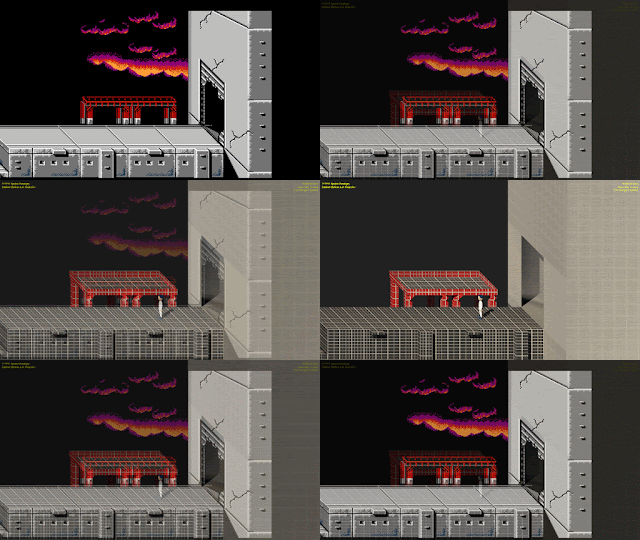
The two different towers shown in the image are projected by different methods. The smaller, boxy towers use the same cabinet oblique projection as much of the rest of the environment. This is a paraline projection where receding lines are all in parallel (see the yellow lines in the image). The larger towers on girders use a naive perspective projection that is similar to 1-point perspective, but the receding lines do not quite converge on the same vanishing point (see the cyan lines in the image). The roof is approximately in 1-point perspective, but the floor uses an oblique projection. The two combine into a naive perspective with opposite oblique projections that approximate receding lines that converge in the distance. This is why the larger towers look strange in my project when rendered in cabinet oblique projection.

Dream of the Palace (Giotto di Bondone, 1297-1300)

Naive perspective is often seen in western art before Alberti published Della Pittura (1435), detailing the methods of linear perspective developed by Brunelleschi during the Italian Renaissance. Artists like Giotto painted buildings with roughly converging receding lines (or orthogonals) to approximate a perspectival view.

Art and Representation (Willats, John, 1997, pg. 64)

As seen in John Willats' analysis above, there is a sense of a horizon line near the center of Giotto's palace, where the receding lines are horizontal on the picture plane. Each floor of the palace is painted at an oblique angle tilted toward that horizon line. These receding lines do not converge and do not form a linear perspective.

Level End and Beyond

The end of the level leads into a large building through what appears to be a breeched garage door. This serves as a transition to Area 2, First Base in which the view becomes planometric naive perspective (with a bird's eye view looking down at the floor). Area 3, Jungle changes again with an elevation vertical oblique projection. Area 4, Inner Base starts with elevation cabinet oblique right projection followed by elevation naive perspective. Area 5, The Cliff starts at elevation vertical oblique projection, then switches to elevation cabinet oblique right projection (note that Area 1 is left projection). All of the first five levels of this game use different projection methods for their environment art assets.

A question that may be asked here is why? There are several possible reasons. One may be a desire for visual variety. This makes sense with the variety of navigational gameplay in different levels (horizontal side scrolling elevation view, vertical scrolling elevation view, vertical scrolling planometric view). Another possibility is that different artists worked on different levels (although I think that Setsu Muraki was the only artist for game graphics).

Thursday, August 15, 2024

Building the World of Super C

Taxonomy of Virtual Spaces Part II

My second platformer game world is Area 1, Fort Firestorm from Super C (Konami, 1988). I am creating the world in 3-D after analyzing the level's cabinet oblique projection, which gives some sense of depth into screen space and dimensionality to the game world.

Comparison between Super C and my project

As can be seen in the gif above, I have been recreating the game world of Fort Firestorm in 3-D. I spent some time tuning and adjusting the camera settings so now the cabinet oblique projection seen in the game is perfectly recreated.*


Yoshi's Island graphic distortion analysis by destroyerofseconds Source

Super Metroid graphic distortion analysis by destroyerofseconds Source

* Almost perfect, that is. As I've written about before, there is a difference between a "pixel-perfect" image of NES or SNES graphics (such as is displayed on most emulators) and how those graphics would look on a CRT screen. The full graphic resolution for both systems is 256 x 240 (an 8:7 aspect ratio) that would be stretched horizontally, with "wide pixels," to display at a 4:3 aspect ratio on a standard definition television. That means that the 45 degree angle of the receding lines of the cabinet oblique projection in Super C should be at a smaller angle in order to be screen-perfect.

However, there is evidence that many Nintendo artists did not take this aspect ratio distortion into account when creating their graphics. This is most noticeable with objects that are perfect circles. As seen in the images above, the circles in these two first-party Super Nintendo games look correct at 8:7 ratio, but become distorted at the 4:3 ratio they would be seen in by the player (note that NES and SNES both have the same graphic resolution).

Tuesday, August 13, 2024

Analyzing the Spatial Construction of Super C

Taxonomy of Virtual Spaces Part II

The Super Mario Bros. World 1-1 replica is working well in my project, but the original game doesn't have much of a sense of depth into screen space. There are some hills, clouds, bushes, castles, fences, and horsehair plants in the background, but it is difficult to get a sense of how far these objects are from the player's path. I am able to infer some implied depth from objects like warp pipes, but the game's orthographic projection makes everything appear very flat.

For my second game world, I turn to another NES classic, Super C (Konami, 1988), the sequel to the original Contra and a port of Konami's arcade game Super Contra (1988). [Why did Konami name this game Super C instead of Super Contra in the USA? It is assumed that it was to avoid comparison to Ronald Reagan's Iran-Contra scandal that had recently been exposed.] I have written about Super C before as an example of a game with elevation oblique projection. The game actually has a wide variety of visuo-spatial configurations with different styles of gameplay in different levels, but I want to concentrate on Area 1, Fort Firestorm.

Super C Area 1, Fort Firestorm

What is Oblique Projection?

With an oblique projection, the front face of an object that is parallel to the picture plane (in this case, the dark wall below the ground plane) is represented in its true shape, just like an orthographic projection. However, unlike orthographic projections where the projectors are perpendicular to the picture plane, oblique projectors are at an oblique angle to the picture plane (remember that this uses the Primary Geometry projection model). Therefore, two other sides of the object are also visible, but their shapes are distorted (read my other posts for more on the historic confusion between axonometric and oblique terminology).


The receding lines of the object are foreshortened (or not) by a certain amount depending on the angle of the projectors from the picture plane. Cavalier Projection is when the projectors are at 45° and the foreshortening ratio is 1:1 (in other words, no foreshortening). Cabinet Projection is when the projectors are at arccot(1/2) (about 64°) and the foreshortening ratio is 1:2 (receding lines are drawn at 1/2 normal length. These are older methods of creating technical drawings for the military (cavalier) or furniture industry (cabinet) and are designed for preserving object measurements, not for their aesthetic qualities. For a less distorted image, a foreshortening ratio of 2/3 or 3/4 would be more pleasing to the eye ("Planar Geometric Projections and Viewing Transformations" by Ingrid Carlbom and Joseph Paciorek, Computing Surveys, vol. 10, no. 4 (1978) pg. 482).

What Kind of Oblique Projection is Fort Firestorm?

What would these floor sections look like from an overhead view?

The game's imagery must be analyzed before I can determine how to recreate the world with 3-D models. How wide is the player's path? Characters are about the same size on the screen as in Super Mario Bros. so I can keep the general scale the same (measured in 16 x 16 pixel "blocks" that translate to Unity square meters).

In the image above, the large gray rhombus shapes on the player path look like they are obliquely distorted square shapes to me, reminiscent of the square slabs of a sidewalk. The long edge of each rhombus (the non-foreshortened edge) is exactly 64 pixels. The short edge (the foreshortened edge) is almost exactly 32 pixels. This gives a 1:2 foreshortening ratio, which is a Cabinet Projection. The exact type of oblique projection is not important, but this gives me a ratio to determine the size of the "gutters" and projections along the edge of the player path. On the right of the above image, I show what an overhead view of the player path would look like if seen from directly overhead.

With these measurements, I can easily recreate the main player path of the level in 3-D.

Wednesday, August 7, 2024

Changing Projections Mid-Game

Taxonomy of Virtual Spaces Part II

My latest update added functionality of varying levels of importance to my project. First, the level will reset if the player character falls off of the screen, adding some challenge of avoiding the "death fall" pits in the game world. Second, I can now take screen shots from the editor play window by pressing the "I" key. Most importantly, third, the game's projection method can be dynamically changed during play

This represents a "minimum viable product" of my project for visualizing different visuo-spatial configurations within the same game world. The following examples are taken from my "family tree" of projection methods that define the graphic techniques used to render images onto the screen. All of the following projection methods may be cycled through without interrupting gameplay.

Orthogonal Projections

Orthographic Projection

2-Faced Oblique Projections

Vertical Oblique Projection

Horizontal Oblique Projection

Elevation Oblique Projections

Cabinet Oblique Right Projection

Cabinet Oblique Left Projection

Cavalier Oblique Right Projection

Cavalier Oblique Left Projection

Perspectival (Linear) Projection 

One-Point Perspective


Tuesday, August 6, 2024

Framing the World

Taxonomy of Virtual Spaces Part II

An important aspect of my "Taxonomy of Virtual Spaces" (Rowe, unpublished) system for analyzing digital environment aesthetics is in defining how the world is framed by the screen. As I detailed in a previous blog post, the concept of the screen as a framing device or "window" through which a player observes a virtual world is one formalized by Clara Fernández-Vara, José Pablo Zagal, and Michael Mateas. In paper published through DiGRA, they state that “The screen is the basic unit of space in videogames, since it frames the interface” (Fernández-Vara et al., "Evolution of Spatial Configurations In Videogames," 2005). The screen can act as a yardstick by which we can measure the virtual space, one screen at a time, at least in most 2-D games.
The screen's parameters and motions are often described in camera terms, like a tracking shot following the player character or zooming in on a target. I argue that 2-D games do not have a concept of a game camera, which would imply a view from a fixed station point (the oculus). 2-D use paraline projections instead of perspectival views and there is no station point. The Unity game engine still uses an allegorical "orthographic camera" object to act as framing device for 2-D games, but does not construct an image of the world the way a camera or an eyeball would.

Virtual Worlds of the NES

BG Planning Sheet used in developing Super Mario Bros.

Nintendo's Famicom/NES game console was capable of displaying a 256 x 240 pixel image on a standard definition, 480i resolution screen with a 4 x 3 aspect ratio. These pixels are slightly wider than they are tall due to the fact that 256:240 is not exactly a 4:3 ratio, so they are stretched horizontally. Game backgrounds are typically divided into 16 x 16 pixel tiles (in truth, 16 x 16 metatiles created from four 8 x 8 tiles), so one screen is 16 tiles wide and 15 tiles high.

Blank BG Planning Sheet from Nintendo

Game developers at Nintendo used an internal form called a BG (background) Planning Sheet when devising the graphics for their games. This form includes a grid 16 tiles wide and 15 tiles high to represent the graphics that can fit on one screen. A CRT television would often have a bezel around the screen that would obscure part of the image, so important objects and data could only be shown on the TV's "tile-safe area" away from the edge of the display. You can see plus signs (+) marking the corners of this area on the sheet above.

Converting to 16 x 9

Mega Man (1987, Capcom) and Shovel Knight (2014, Yacht Club Games)

Yacht Club Games wanted to emulate the look and feel of NES platformer games like Mega Man in their own Shovel Knight. They faced the same problem: how to convert the graphics designed for a 240 pixel tall 4:3 display to a high definition 1080 pixel tall 16:9 display? They solved this by a method they call "breaking the NES." Each "pixel" of graphics in the game is displayed at 4.5 x 4.5 pixels. 1080/4.5=240, giving a effective vertical resolution of 240 pixels. Keeping the same vertical resolution of the NES gives them a 400 x 240 widescreen display area. Screens are still designed to be 15 tiles tall, but can extend further left and right than NES games. See the image above to see Shovel Knight side-by-side with original NES graphics. Yacht Club Games doesn't have to worry so much about a TV's tile-safe area, so they can display text much closer to the edge of the screen than NES developers could.

Super Mario Bros. and my project

This is the approach I've taken with my project as well. I am not trying to emulate pixel graphics as that is not the focus of my research, but I am copying the same vertical screen heights of objects (characters, obstacles, blocks) as seen in NES era platformer games. This preserves the size of objects on the screen, even when displaying on a 16 x 9 monitor.

New Game Launched and Summer 2024 Research Review

Summer 2024 Review Taxonomy of Virtual Spaces Click here to play the new Taxonomy of Virtual Spaces - Expanded Edition interactive project...